These are helpful hints that I either discovered or were given to me by other builders or my EAA Technical Counselor, or are answers to questions I asked Murphy Technical Support.
1. The control horn must definitely be reamed out to get the lower upper control tube into it. A brake honner worked very well to take out the required material from the inside of the control horn.
2. Before you rivet the curved cockpit cross braces in place, think about how you will get your riveter between it and the upper longeron to rivet the inside cabane strut brackets. It may help to just clecoe it in place until the brackets are riveted.
3. The front control stick comes too far back into the front passenger's lap if installed per the diagram. I turned it around to curve away from the front seat, and that gave the necessary clearance, while still providing easy reach for the front pilot.
4. The supplied bolt for the lower control tube to stop the rearward pull on the stick was 1-1/4" instead of the specified 1". This meant the stick couldn't go far enough back to get the full +/- 25degree travel on the elevator. Some other adjustments will need to be made. I haven't yet decided whether to use the shorter bolt or to do something else, like shorten the rear stick or limit how far the back of the front seat back can move, or a combination.
5. Deburring the small 1/8" holes inside of tubing is difficult with the commercially available deburring tools. But if you take a regular finishing nail, bend the end of it, and sharpen both sides into a blade like the commercial tool, it fits very nicely into the small holes and lets you deburr the inside of them.
6. The nylon washers called for in the control column assembly are really the plastic drain grommets supplied in the materials kit.
7. If you order the large wheels for your Renegade, you will find that the drawings don't exactly show how that option goes together. But it is fairly straight forward and I will have detail pictures here in the future on how it actually looks. A drill press works great for drilling the 2 holes in each 1 inch thick axle for mounting to the bungee gear struts. Shaping the bottom of the main gear struts to fit the curve of the top of the axle will let you drill the axle holes a little closer to the center line of the axle. Offset shaping the bottom of the bungee strut will let you place the inside hole a little further from the end of the axle. Future pictures in the Landing Gear page will detail this.
8. Before you rivet the fuselage front "V" braces inplace, plan on how you will manuever the front floorboard into position after it is varnished. It is a very tight fit, especially after those front braces are in.
9. Rear rudder pedal placement is truely a matter of personal preference. There are lots of suggestions out there, but everybody likes a little different amount of knee bend in normal flying position, so what works perfectly for one builder, will be too much of a reach for another builder of exactly the same stature. Sit in the cockpit and have someone hold the rudder pedals in different positions for a while. When you think you have just the right spot, try it out again the next day.
10. The same advice goes for the throttle placement. Clamp the throttle assembly in different positions and sit in the cockpit with the seat where you want it, and try it out several times before you drill the holes in the throttle backing plates, or even cut and mount those plates. Move it up and down as well as back and forth, to see what is most comfortable for you with your seats and rudder pedals where you want them. Remember that as the rudder pedal mounting position moves back, your knee moves up and you might want the throttle assembly an inch or so higher or maybe further back. Take lots of time finding a good position for these things as you will be flying them for a long time. Those quick connect clamps make trying lots of optional positions a lot easier.
11. When you are ready to drill and install the curved tail spring, the longer part bolts to the fuselage and the shorter part bolts to the tailwheel. A drill press makes it real easy to drill a perpendicular hole straight through those very thick aluminum pieces. I use a small bench top drill press which works just fine.
12. The brake calipers can be fed fluid from either direction. The drawings supplied with the wheel kits will show you how to assemble the calipers and how the wheel assemblies go together. Our bearings are lubricated here and are ready for installation. Obviously you still want to check such things anyway. Your axle is special order and is only 1" thick where it mounts to the bungee gear. The heavier Rebel's is 1.25". Preferably align the calipers at 45 degrees back side of the axle to allow for the gear travel as well as for protection.
13. Q. How do you make the holes in the rudder peddles? I did one with a drill and jig saw - it took 4 hrs to do the first one and its not even perfectly round.
A. A large hole saw on a mandrel. I put it in my drill press for stability, but you could clamp the peddle down and use a drill. The bimetal hole saws from home depot or the wholesale tool supply work fine. They aren't real cheap, and I got a number of different sizes for different parts of the plane like the ailerons. Plumbing or other commercial grade hole saws work well. The bi-metal ones cut through the alumnium fairly clean. Then just use your deburring tool to dress up the edges.
14. Q. I was just looking at your pictures again - their better than the manual, and I was wondering if you received a special part for the elevator bumper? Is that what I see in picture "elevator16". It also looks like you put the trim tab on the right side. Is that so you can keep one hand on the throttle and one on the trim?
A. I think what you are seeing is my Rivnut installation tool for which I am using an adjustable wrench and an allen wrench. /the rivnut gets a bolt with a stop nut that hits against the fin post. I later cut out a piece of pvc pipe to rivet against the fin post where the stop bumper hits it. The elevator horn needs to have a hole drilled for the rivnut.
I think the trim tab instructions said to put the handle on the right side, but I was getting too much stuff on the left anyway. The cable will need to reroute up under the turtledeck because it is pretty long. Others have mounted the trim tab control under the throttle on the left side. Personal preference rules here.
15. I was just admiring your photo's of your construction process. My quick build kit will be shipped on Sept 15th. and I already have several questions.
How did you get the kit off your trailer and into your work shop? I had the crate delivered to the shipping company's terminal about 20 miles away, not to my house because I had no way to unload it. Then I used my utility trailer with a little extension to pick it up at the freight terminal. They used 2 forklifts to bring it out and maneuver it onto my flat trailer. Then I safety strapped it down real good, and drove home slowly. The crate sat on the trailer in my garage until I had unpacked and inventoried everything, storing all the parts as I unpacked them. Then my kids talked me into putting the empty crate out by their tree house as a "basement". If I had to get the full crated off the trailer, I would have tilted the trailer back, tied the crate to the back of the workshop structure, and slowly pulled the trailer out from under it with my truck. You would need to rig something to keep it from dropping the last few inches (maybe some 2x4s). But as I said, I backed the trailer into the garage and unpacked it first. A drill operated Philips screwdriver is a must to remove the screws holding the crate together. I reused the screws to hold wood jig blocks in place.
16. I saw a rivet gun similar to the one your using in a tool catalog. Can you tell me the brand of yours and where you got it; most of all did it work OK? I bought the pneumatic rivet guns from Harbor Freight Tools Catalog. They work great once you learn which tips to use with which rivets. I ended up with 2 guns, an "aircraft" one and a regular duty one, so I could stop changing tips all the time - you have 8000 or so rivets. The mandrels sometimes do get jammed, and you have to open up the head like you were changing tips. The 3/16" ones, especially the stainless steel, are almost impossible to put by hand, but there are a few places I had to do it because my air riveter was too big and fat. My rivet guns are made by Central Pneumatic (an import) and purchased thru www.harborfreight.com . They send tons of free catalogs with varying prices. I usually call in the orders.
17. Can you tell me how many of each Cleco you really needed for construction. I have close to a hundred of the 1/8" clecoes, and maybe 20 or so 3/16". that is all I have used so far. The 1/8" ones get used a lot almost everywhere except the fuselage.
18. I hope these don't sound like stupid questions and you will take the time to assist me. Have you heard about the Yahoo club for Renegades builders? Its small but has plenty of useful info. The only stupid questions are the ones that don't get asked. I send a lot of emails to Murphy Technical Support, and they respond usually the same day or the next day. Also there is completed Renegade Spirit near where I live
19. I really appreciate the input. It is quite useful. My kit will be shipped on Sept 15th and I am on the edge of my chair waiting. Have you picked an engine ? I haven't decided on one yet, but I figure I have plenty of time.
I will use the 100hp Rotax 912ULS. Murphy supplied the engine mount and I'll get the engine from the best deal when I'm ready to buy. . A local friend has the 80hp Rotax 912 in his Renegade Spirit and reports somewhat sluggish takeoffs on our hot humid summer afternoons, so the few extra hp should help. Flight is just fine with his 912. He does lots of aerobatics.
20. Read the assembly manual cover to cover before you start making anything.
21. Murphy sent me their Rebel work table plans if you haven't set up a table for construction yet. Flat, level, and dimensionally stable is more important than heavy load capability. None of the components are very heavy, but you don't want your table to warp or bend, so I used 3/4" plywood cut in 8" and 6" strips for the supports instead of 2x4s and 2x6s.
22. Remember that the front rudder peddle springs attach to the gussets in the front bottom corners of the fuselage, so don't trim them before looking at the manual to see the exact attach point.
23. I'm still working on the first wing. The aileron bellcrank bearing provided is a new design that takes a 5/16" bolt, but the manual still shows 1/4", so the bushings and the doublers on the drag brace need to get drilled to 5/16" also. I think I need to get a couple of the longer AN5-32A bolts since the -30A doesn't make it through the nut, especially with the extra washers(spacers) I put on each side of the bearing for clearance. The bearing needs to use 12 of the SS rivets shown on the drawing.
24. I'm also starting to determine the location for shoulder harness holes in the back of the turtledeck. It seems staright forward, but I'm checking that the cables to the tail don't press on the top fuselage cross braces.
25. I read your "tips" on putting the axles on the struts and it answered a specific question I had, but.... I have another one. The valve stem on the tube will not reach the hole on the wheel where you would fill the tube with air. Did you have to drill out the top of the drum so that the stem would reach the outside of the wheel? No, do not drill the drum. I went to the auto parts store and bought 2 valve stem extenders. It worked great. Too bad the tubes didn't come with long enough valve stems, but it was at least a cheap and easy work around.
26. I am building the experimental category Renegade Spirit and planning to do lots of aerobatics. The manual and plans indicate drilling lots of lightening hole in the aileron spars and wing spars for the ultralight version. Does this cause a loss of strength and G loading capability that would make it NOT a good idea for me to put all those lightening hole in my experimental category version?
Most people do the lightening to keep the weight down, which equates to more strength, but its not necessary in the experimental version. Just remember to stick RIGIDLY to the aerobatic weight...this ain't a Pits!
27. I am rigging the tail section on my Renegade now and I have some turnbuckle questions. On your Renegade, you have a turnbuckle on each of the 2 cables on the right side below the stabilizer. And did you put any turnbuckles on the cables above the stabilizer that connect the stabilizer to the top of the fin? Did you also put turnbuckles on the cables on the left side below the stabilizer? When attaching the tail assembly cables on page 95, are the AN130-8S and AN130-16S turnbuckles supposed to be put on both the left and right side cables below the horizontal stabilizer? I ask because the material list only shipped one of each for the tail section. All the other turnbuckles supplied are used on the wing wire and cabane assembly rigging. Are they are needed on both sides which would make sense to me?
I put turnbuckles on all four lower tail cables. One end of each turnbuckle attaches to a cable end, while the other end of each are held to the fuselage crossover with a clevis pin. There are two different O.D. cables so I used different size turnbuckles. The upper cables are fixed length but can be adjusted by placing washers under the SS tangs.
28. Page 32 says to run the rudder cable thru 4 guides on each side. 10 cable guides are provided and it looks like there are actually 5 logical places to attach them on each side (one at each upright tube). Is this the current plan or is there another use for the 2 other cable guides that I haven't found yet? The rudders are the only cable activated controls and there are as you said 5 logical locations per side. Use the extra guides were you feel they are best suited. If need be other guides can be secured.
29. The LG-30-1 tailskid is bent with a longer end and a shorter end. Does the longer end bolt up to the bottom of the fuselage or down to the tailwheel? Also, does the larger wheels (8.00 x 6) and hubs that I have in my kit have a heavier load rating than the standard wheels? If so what is that weight rating? Do you use regular automotive axle bearing grease on these hubs or a special aircraft grade grease?
The tailspring goes on with the long end mounted to the fuselage. This is not as important on the Renegade's as on the Rebels where the distance between the attach points is longer and requires a longer straight section on the spring. I don't know which 600 X 8 tires you received but the load rating should be on them. All of the 600 X 6 rims are the same and mount either 600 X 6 or X 8 or X 8.5 tires.
The load rating of the tire and rims is not a concern for you. The landing gear itself is the determining factor for failure.
High quality Automotive Synthetic Grease is recommended for the wheel bearings as it is more tolerate of moisture contamination and has a wider temperature operating range.
30. The instructions for the Renegade Spirit control column assembly call for 24 nylon washers that are used on the pivoting parts of the assembly. There are no nylon washers on the materials list, but there are 132 plastic drain washers. Are the plastic drain washers (1/4" hole ) intended to be used where the nylon washers are called for on the 3/16" bolts?
Yes the plastic drain grommets are what we have been using for the last 15 years they work quite well to date no problems have occurred with them in this application. They are also very cheap to replace if they wear out.
31. I am working on the landing gear wheels and brakes. I have the large wheels with MURBRK Murphy Brake Kit HB (REN) . It looks like the back part of the LG axle replaces the LG-11 piece in the drawing on page 19. Per the full size drawing #7, it looks like the LG axle back piece just gets located as close to LG-7 along the LG-2 as possible and still have clearance. I assume the 1/4" mounting holes should be centered in the axle shaft lining up with the holes in LG-2. Both brake calipers have the plug and the bleeder mounted the same. Is the caliper symmetrical inside so that I can just switch the plug and the bleeder on one of them so that when I attach the brakeline to where the plug is, they will both be on the back side of the axle per page 18? Should the calipers be aligned on the TOP of the axle or at 45 degrees to the front or back of the axle? Is there any advantage to either position? Or is there a better idea? It looks like the wheel assembly has been fully assembled and torqued?, Were the bearings greased? I'll need to remove the axle nut and slide everything out a bit to put the 13A mounting bolts in and then retorque the axle nut?
The brake calipers can be fed fluid from either direction. You have figured out the gear mounting correctly. The drawings I have attached in 2 word documents will show you how to assemble the calipers and how the wheel assemblies go together. Our bearings are lubricated here and are ready for installation. Obviously you still want to check such things anyway. Your axle is special order and is only 1" thick where it mounts to the bungee gear. The heavier Rebel's is 1.25". Preferably align the calipers at 45 degrees back side of the axle to allow for the gear travel as well as for protection.
32. Q. I was looking at the brake cylinders and I don't see any logical way to mount them on the plane. What did you do?
A. Below is the same question I asked Murphy, and their reply. I assume you mean the 2 brake master cylinders that have the plunger on them. I removed the fork and put the round flat disc on for the heel brake peddle. Then I determined where the heel pedal needed to stick through the hole in the rudder pdeal. At the end toward the front of the plane I used 2 "L" brackets to hold a horizontal bolt that goes through one of the holes at the very end of the brake cyl., and bolted the "L" brackets to the floorboard. The brake cyl can pivot up & down on this bolt until you determine the angle to set it at and attach the front. I made another "L" bracket that I riveted to the front carry through and used a vertical bolt through a hole I drilled in the flat rectangular part of the brake cyl near where the plastic hydraulic plugs are. Murphy says below it is ok to drill them, just stay well clear of anyplace they already have holes, passages, and other moving pistons.
Q. I have looked at the brake peddle installation instruction diagrams on pages 32a and 33, and at the master cylinder installation photo in the back of the assembly manual. I looks like the master cylinder attaches to the floorboard by an aluminum angle that is bolted to both the floor and to the master cylinder. However the master cylinder # MC-4A supplied from MATCO has only perpendicular holes in the 9/16" long shaft at the back end of the unit. There are no holes in the sides of the unit as indicated in the drawings, and the block has internal fluid holes so it probably can't be drilled.
A. Those master cylinders can actually be drilled. You can put a couple of holes in the cylindrical (really the square part) section that takes the fittings, placed between these threaded ports. (see Matco drawing). I used to make up a couple of mounting brackets from 1/8" window aluminum angle, bolt them to the floor boards using a hefty doubler underneath, and drill them once I had set the angle for the cylinders where they come through the rudder pedal.
I could just secure the back end with 1 bolt to the floor and then maybe make a bracket to go over the whole unit to secure it against a properly angled block of wood to the floor board. What do you think?
Also, the moveable shaft has a threaded U shaped fitting on the end instead of the flat round disc for your heal to press on the brakes that is shown in the diagram. Is there supposed to be another piece that attaches for the heal to press on, or have I just overlooked more info in another part of the manual or the drawings? 2/ The forks on the ends of the shafts are removed and replaced with a flat, turned aluminum disk, which should be in your kit.
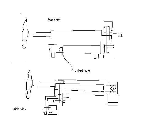
33. Q. Just finished trial fitting the turtle deck and it fits Ok at the ends of the plane, but it doesn't fit around the cockpit compartments. I won't be able easily to rivet the inside of the glass to the inside structure of the cockpit. Was yours the same? did you do anything to try to get it to fit better? Grant said to not worry about it. I kind of worry that pressing down on the top of the turtle deck at the sides of the cockpit will eventually pop the rivets as I climb into the airplane.
A. I had the same fit. Alan Harp who built a Spirit about 6
years ago used a short piece of partially crushed round tubing ( you will eventually have
some left over from the wing aileron control rods) as a spacer about 1/2" thick at
the sides and back of the inside of each cockpit. You could also use 1/2" square
tubing. I used short pieces of left over trailing edge channel on the sides and on the
back of the rear cockpit (the angle seemed to be a natural fit with the opening facing
down). I used 1/2" square tubing on the back of the front cockpit so it would not
stick up and obstruct the already tight instrument space for the rear cockpit. You will
have to cut out 3 or 4 larger holes(see drawing) where the tubing touches
the fiberglass so you can rivet the other side of the tubing to the metal cockpit
structural tubing. The rivet gun tip will determine how much to cut out or grind out- a
dremmel type tool can smooth the rough edges. The turtledeck has to be off to attach
the scrap tubing to the cockpit metal structure. see drawing. 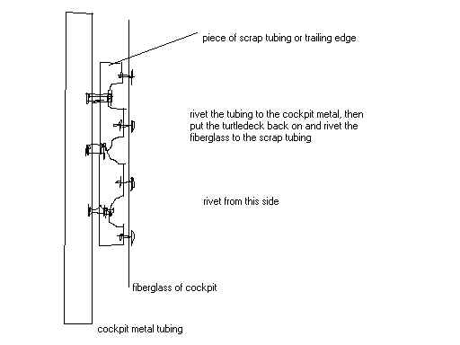
I don't have any photos of this yet, my scrap spacers are attached to the cockpit but I haven't riveted on the turtledeck. I didn't use any extra support on the front of the cockpits as I will be cutting a section out to make removeable instrument panels.